For those of you who are unfamiliar with the term “wall wart” it is simply a slang term for external power supply’s that hang out of the outlet. The power supply has evolved over the years from being something external to the apparatus to be powered, cabled to same with large cables.
As technology “evolved” the power supply was integrated into the apparatus and a simple cord connecting it to the AC line was all that was needed.
After even more “evolution” the power supply went external again on some apparatus’s in the form of a wall wart.
It was during this time the wall wart was blamed for starting fires. Many firefighters attributed the source of combustion to the wall wart.
Early wall warts were not fused or if they were the fuses were defective. I still vividly remember smelling something “like hot plastic,” finding a wall wart going to a radio was melted, very hot and still pumping out energy into a short length of cable that the cat had chewed on causing a short.
These power supplies still use energy even if the apparatus is powered off. Those “green” people will tell you to unplug them when not in use as they waste energy. I would tell you to unplug them simply because “in my opinion” they are still a fire hazard.
Unplugging them can be a pain in the rear as often times they are buried behind something etc. To this I would encourage you to get a power strip that you could turn off the whole thing when not in use rather than trying to plug and unplug every time you wanted to use the device.
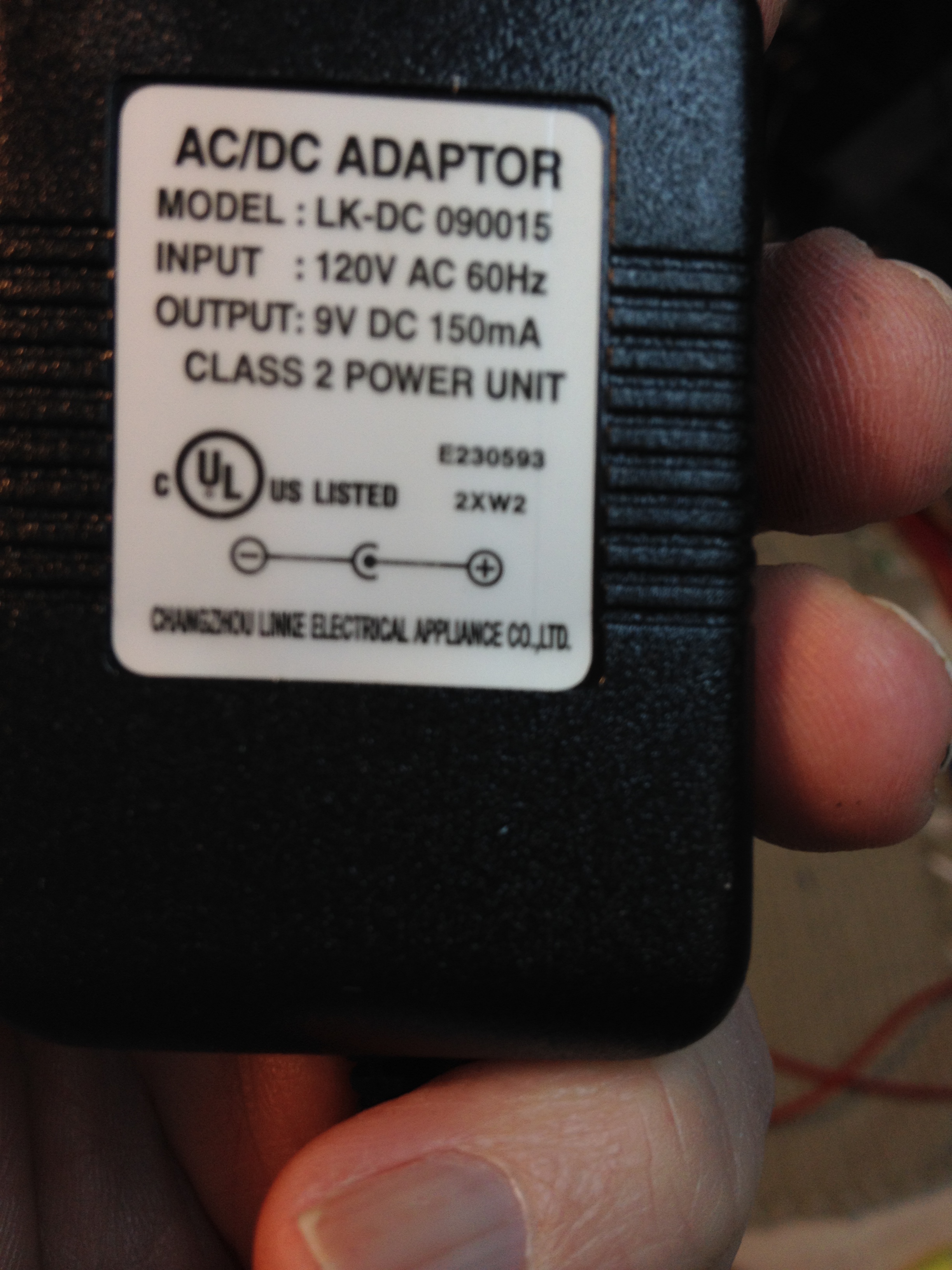
Case in point. My phone stopped working. When I did my “electronic technician thing” I discovered that the wall wart was dead.
Finding a similar wall wart today has not been successful. It is a 7.5 volt with a current rating of a 1000ma. The real trick is finding one with a 90 degree bend in the plug as to fit into the bottom of the base.

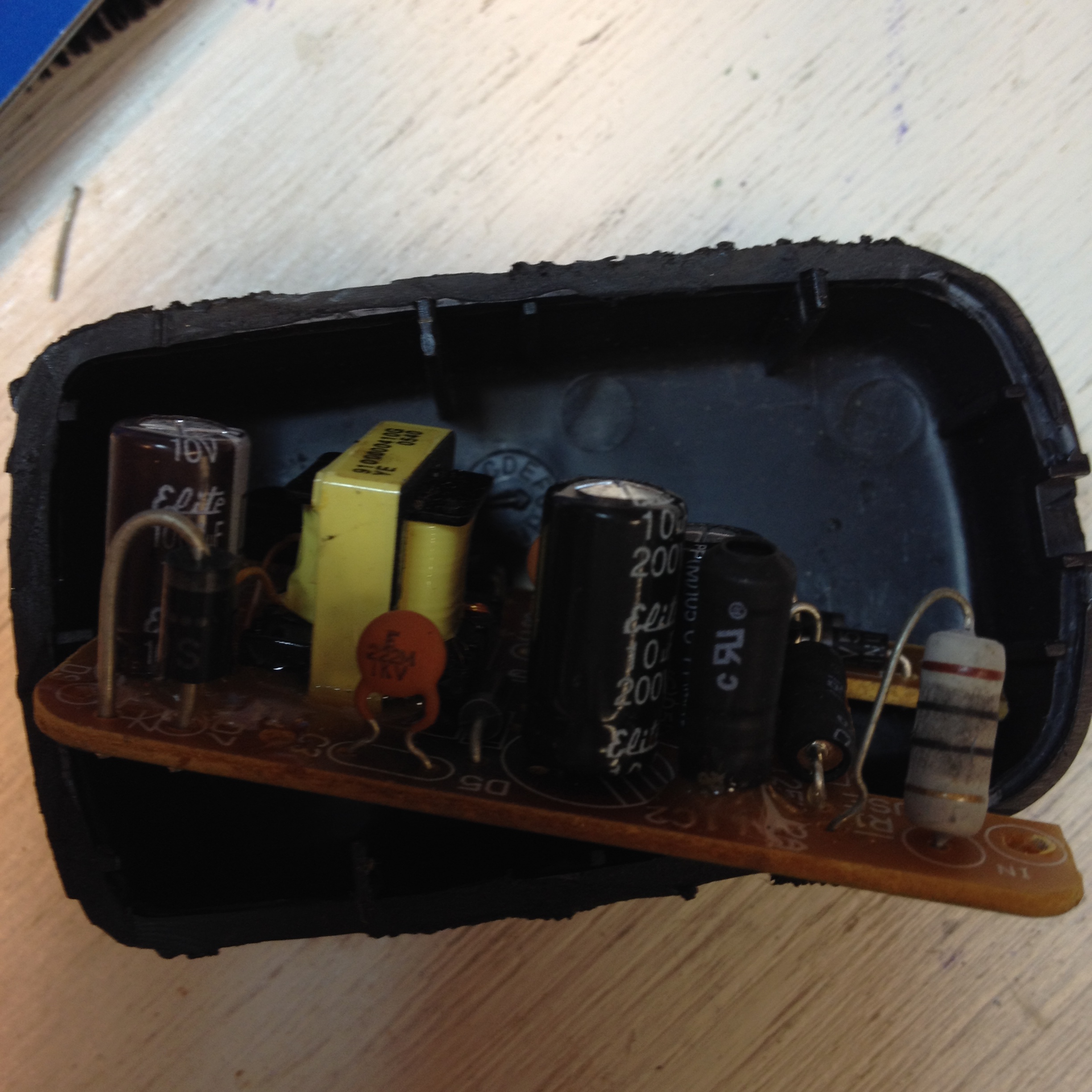
Looking at the wall wart “I dissected it,” the failure was a capacitor that failed. This should not be any surprise to those of us who work with electronics as there is a raft of faulty capacitors in the marketplace which are responsible for the early demise of many many things! From computer power supplies to flat screen TV’s to just about any electrical device made in China. Read all about that subject here. http://www.badcaps.net/
This too made a smell which alerted me to the fact that something was awry. The interesting part of this is the internal fuse did not blow. Had I not been home and smelled the “hot smell,” would my house still be here?

Because it is in an airtight container one has to think that any flame would have not had the oxygen to burn and eventually the fuse might have blown or the circuit breaker to the receptacle might have tripped. The short answer is “we just don’t know.”
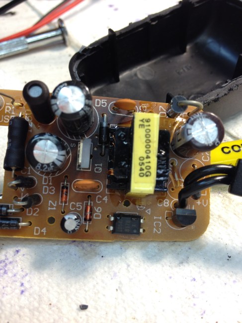
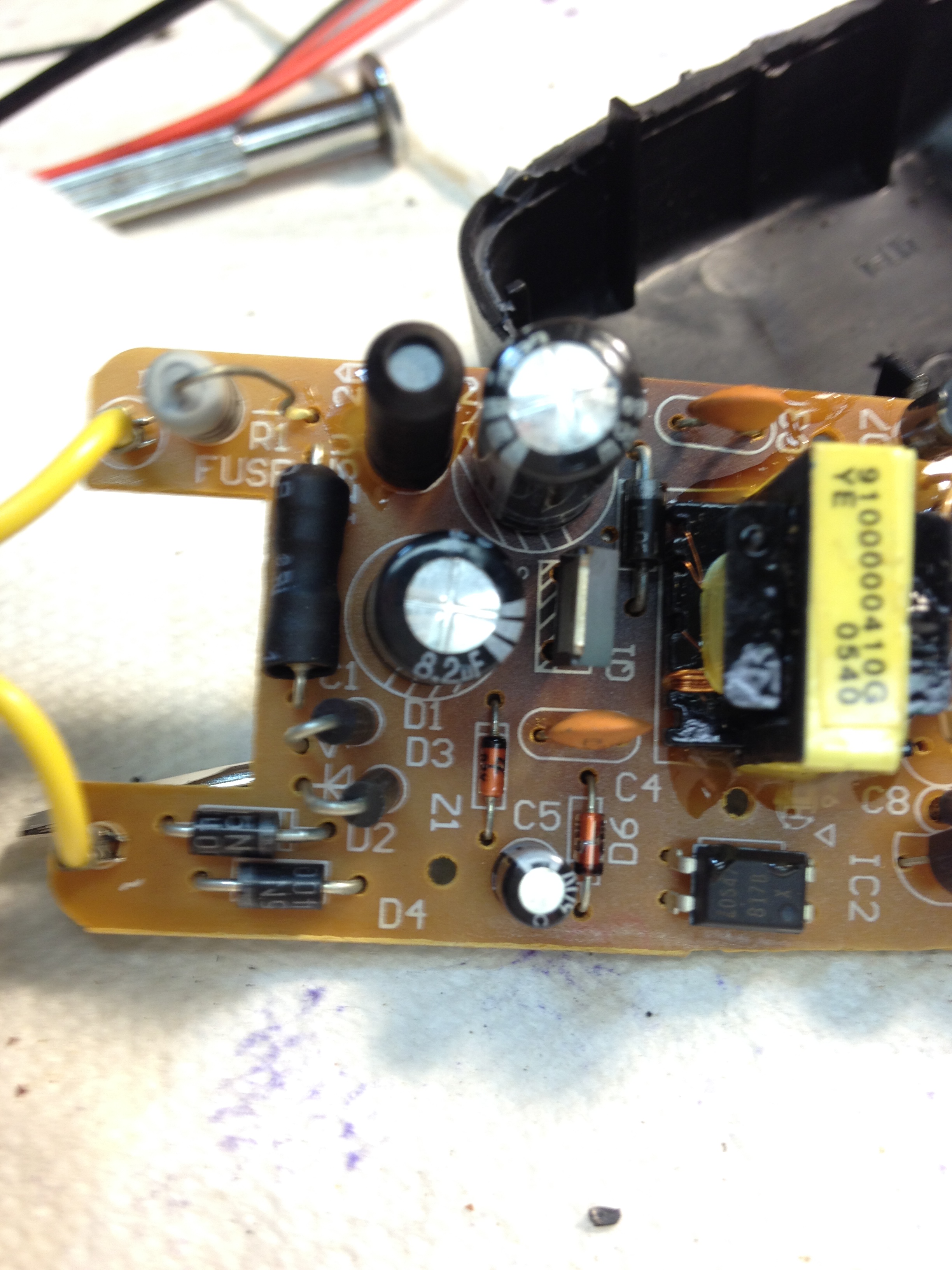
Looking at the device you can see that they have dropped the 120V to 12V with a large 10ohm resistor. From there they have rectified it, regulated it and I would guess cleaned up the dc and even the AC with a few small components. You will note the top of the capacitor is puffed up which is a clear sign that it is defective. You will also note that the board is discolored where the devices got hot when the capacitor failed.

All Wall Warts are not the same!
I frequently am asked by different people to repair some small appliance. I enjoy doing it so it is not much of a burden. More often than not I am brought the device that no longer works with a wall wart that is not the correct wall wart for the device!
Looking at the back of the apparatus you will notice that there is just about always a picture or depiction of the place that the wall wart plugs into the unit. That depiction will usually have the voltage and current required as well as the polarity of the plug.


Back not too long ago it was anyone’s guess if the center was positive or negative and, the information about the voltage, current or even if it were AC or DC was just not there.
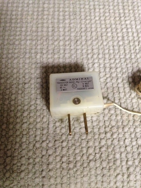
Looking at this early wall wart “from the 70’s” you will note that it is small in size and has a plug on it that when inserted into the radio momentarily is greeted with a short. This type of plug should not be used for power. This charger is rated at 9volts dc with just a few mils of current. The reason for this is it was designed not to run the radio but to charge the batteries inside it. While the radio that this goes to is otherwise a good radio this is a poor design. Admiral would have been far better off to include the power supply inside the radio capable of running the radio as well as charging the batteries instead of using this, (which was a cheap alternative.) Also note that the plug is broken and should be repaired before use. Interesting to note: this supply is not regulated and in fact cranks out 21volts DC with no load.

With older devices I have to check before simply plugging in some sort of power source as some of the older radios that I mess with were made before any standards were envisioned.
Some manufactures made positive the ground, which makes an interesting troubleshooting exercise for those of us who are used to negative as the ground.
We all end up with a box of these wall warts before too long and often times they are not labeled as to what they went with. My guess would be that the manufacturer of the device purchased power supplies from some vendor that would work with their device and a host of others.
It is a good idea to label what device that wall wart came with if it is not so labeled on the power supply itself. I have seen some use a silver Sharpe to label them which is a great idea!

Things to note when looking at your apparatus and trying to match up the wall wart. Voltage required, Current required, size and type of connector, polarity if DC, or is it AC?
If you have cats you might want to examine the wires from time to time as some cats or other critters like chewing on cords. For people in this predicament wrap your wires in “spaghetti.” No not pasta but something called spaghetti which is a tough plastic coiled covering designed to keep all the wires together and neat. It also deters small critters from chewing on them. Larger critters may need better solutions like Panduit. I have found some of these things at IKEA. Electrical Supply houses are another good bet and of course there is always eBay.
I would be remiss not to mention your smoke alarm at this point as many of us loose some ability to smell as we age, or have a cold, or what have you.
Feel of your wall warts from time to time, warm is normal, hot is not! Some power supplies for laptops get too warm for my taste, but I think they would tell you it is normal. If in doubt, have it checked out. Safe rather than sorry is not a shabby way to live your life.
Look under the desk from time to time and examine your wires and cords to make sure that they have not been cut by the chair rolling over them or some other heavy object sitting on them. This is especially true of your children’s room. I was in a house doing some computer work when I noticed that there was probably 30 plus amps of current being taken out of one wall receptacle. The wires under the desk looked like a bowl of spaghetti “the eating kind” and there were heavy objects sitting on the wires along with them being under the rollers of the chair.
Wall receptacles in most houses are not made for this type of use. The bedroom may be on one 15 amp breaker and the outlets wired with number 14 wire; which is basically made for lighting. These are all things to look at when putting computers in bedrooms. The good news is that again technology is becoming more efficient and less current is used with newer devices than older. It is still something to talk with an electrician about if you have the slightest cause for concern. The simple fact that this kids breaker did not blow for his room really bothered me in that he had a gaming machine, three monitors and a plasma TV… Add to this the stereo, lights,fans, guitar amp and other electrical things other than this being one spoiled child there was simply too much in that room for what the circuit should have been able to provide.
Feel the outlet covers, are they warm? They should not be….
-Best to you and those that you care about!